


3D-Print Studio
昔から持っていた自転車がまだまだ使えますが、阿蘇がちょっと広いです!坂道もありますがこの自転車には3ギアしかないんです!カリフォルニア産のビーチクルーザー式です。
自転車はまだ綺麗ですので、まだまだ使いたいですね!電動式自転車への変更キットを調べたら、いろいろなバリエーションがありましたが中国産の古いタイプのモーターキットを選びました。
Aso's a little bit hilly since it's on the slopes of an active volcano (!), and my old beach cruiser only has 3 gears - because it's designed for flat beaches, mostly. So I wanted to look into converting my cruiser into an electrically-powered bike, and came across several ways to do it. The cheapest was to fit an external motor to the rear wheel, using a conversion kit from AliExpress (and some extra bits and pieces), and being the cheapskate I am, I decided to try it the cheapest way possible!
▲ 買ったパーツはいろんなところから集めました:
合計約200ドルですので、22,000円ぐらいですね。
In total it came to about $200, with mostly free shipping. Only the batteries themselves required a $20 shipping charge, I think.

▲ このキットはほとんどどの自転車でも利用できますが、私のビーチクルーザ―だけには問題が発生しました。キットのコグがそのまま使えませんでした。穴が36mmですが、私の自転車には後ろにホイールにクルーザーブレーキが付いていますので、48mmの穴が必要でした。ちょっと悩みました。ネットで48mm穴のコグが見つかりませんでしたので、近くのDIY店「ハンズマン」の作業教室でドリル機械が無料で利用できました。写真のように小さい穴を30回ほど開けて、やっと50mmの穴があけました。成功!
The first job was to fit this big metal cog to the rear wheel of my bicycle, but here I found my first (and only) problem.... it didn't fit! The kit only comes with one cog size, which has a 36mm hole in the centre. This usually fits most bikes, apparently, but sadly it did not fit my beach cruiser, as it has a coaster brake built into the centre of the rear wheel (allowing you to brake while having a surfboard under one arm!), and therefore required a 48mm hole.
After no success online finding a replacement cog with a suitably large hole, and no success drilling a large hole in the cog myself, I took my cog to my local DIY store, and used the drill press they had in their free-to-use customer workshop. So I carefully drilled about 30 small holes in a ring, and poked out the centre. Mission accomplished!

▲ 後ろのホイールを外して、そのコグを写真のように付けました。必要な道具がレンチぐらいだけですね。
Back at the house, I removed the rear wheel from the frame, and fitted the metal cog. It simply bolts to the spokes using thick rubber cushions to hold it tightly in place. Easy!

▲ コグ付きのホイールとモーター用の短いチェーンを自転車に付けました。
Then you fit the wheel back on the frame, and don't forget to put the small motor chain inside too!

▲ 次はモーターですね。この黒いブラケットがキットのパーツですので、一般の自転車には利用できます。残りの作業がバッテリーとコントローラーですが、結構簡単ですね。バッグに入れて自転車のフレームに付けます。最後にハンドルバーにスロットルを付けて、ケーブルでつなぎます。これで完成でした。
Next you need to fit the motor's bracket to the frame and make sure the motor's cog lines up nicely with the chain to the rear wheel. It takes a while to make sure it's in the right position so the wheel and chain spin smoothly, without slack, but nothing too hard.
Then it's just a matter of placing the batteries in the big bag, the controller in the small bag, and attaching those to your bicycle. The last part to add is the throttle on the handlebar. When you order the kit, you can either choose a twist-grip throttle that replaces the right-hand rubber grip, or a thumb-push throttle lever. I chose the thumb-push lever, and attached it to the left-hand side of my handlebar - because my gears are already on the right. Then connect up the cables, and you're done! Yay!

▲ 完成の電動式バイクです!右側が結構綺麗ですね。2個のバッグしか見えませんので普通の自転車みたいです。
Here's the completed e-bike. From this side, you can't really even tell its electric, because all you'd see are the two bags in the middle.

▲ 左側にはモーターが見えます。付けたモーターが古い形の「ブラッシュ」タイプですので最新型の電動式自転車と比べたらちょっと音が出ますが、別に問題ないです。
From the left side you can see the motor clamped to the rear wheel. I chose a brushed-type motor (because it was cheapest!) but it does use older technology and does make a small noise when working, but I'm not too bothered. The latest brushless motors are of course quieter, but a little more expensive.
ビデオのように電動だけでも利用できます。2個のバッテリーで大体1時間のフルパワーで使えそうだと思っております。ということは20~30kmほどです。
Above is a quick video showing my first test ride! The bike picks up power nicely, without any pedal assistance, and those two 36V batteries running in parallel should provide enough power for about 1 hour of motor-only cycling.... which is probably somewhere around 20~30km, I think. That's plenty for me, but I guess I could add a third at some point in the future to extend that range if need be.
An excellent step-by-step video guide I found useful:
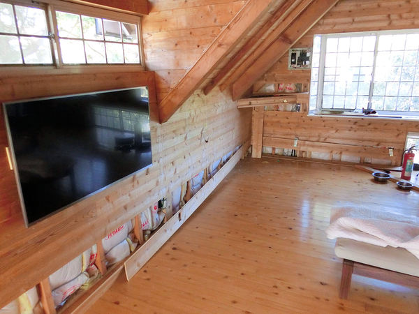
2階リビングの最後の大きい作業になりますが、やっと床暖房を付けようと決めました。エアコン暖房が目にかゆいので、部屋の反対側がまだ寒いので、今回床暖房にします。エアコン暖房と比べたら、電気の床暖房が安いですね。今回2万円ほどの予算です ー 安いでしょう?
ただし、その上に新しい無垢フローリングも付けますので、それだけがちょっと高いですね。どうしてもフローリング買え変えを考えている方にはお勧めです。そしてランニングコストもエアコン暖房より安いです。大きいエアコン暖房は大体5kWですが、今回の床暖房が約3kWで、熱が下から来ますので気持ちいいですよ。
Today's blog is a slightly long how-to guide, detailing how you can make your own DIY underfloor heating system for a low cost, and with great results.
The upstairs living room (and kitchen and office!) is currently heated by a wall airconditioner, which produces enough heat to slowly warm the room, but it also dries out my eyes and only works best on one side of the room. The office on the other side of the room stays pretty chilly. So I've decided to make my own DIY heating system using electric underfloor heating film, for about $200. That's pretty cheap, and it's also cheaper to run, because it uses approximately 3kW of power as compared to the 5kW of the airconditioner. What's more, it will be in the centre of the room, and the heat starts at floor level, so you can lie down on it. All in all, it's just a better and more efficient heating system.
Having said that, you need to place it under the floor, which can be a pain. I'll be covering mine with new flooring for the whole room, which is the expensive part... but if you're renovating a room anyway with new flooring, adding an underfloor heating system is a total no-brainer!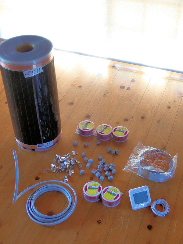
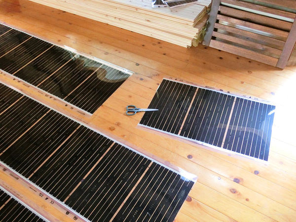
▲ ショッピングリスト:
Here's what you'll need....
110V heating film (top left of the photo). I found that it was much cheaper to buy in bulk directly from the manufacturer, so bought this 100m roll (50cm width) directly from felixkorea.com, which cost $200 plus $160 to ship from Korea. For this large living room I will only be using 30m or so, so I can use the remaining 70m of the roll for other rooms.
Electronic thermostat controller (bottom right). These are as cheap as $15 on Ebay, and work with 100v to 240V systems.
Film crimp clips (centre left). Pack of 40 for $8 on Ebay.
2-core cable (bottom left). 5m for about $20 on Amazon Japan. It connects the fusebox to the controller.
Cable connectors (centre). Box of connectors for $10 on Amazon Japan.
Red/black electrical cord. 6m of 2mm thickness was $7 on Amazon Japan, and I used about 10m for this room.
Waterproof butyl tape (single sided). 50mm width tape is $8 on Amazon Japan for 20m.
How to video:
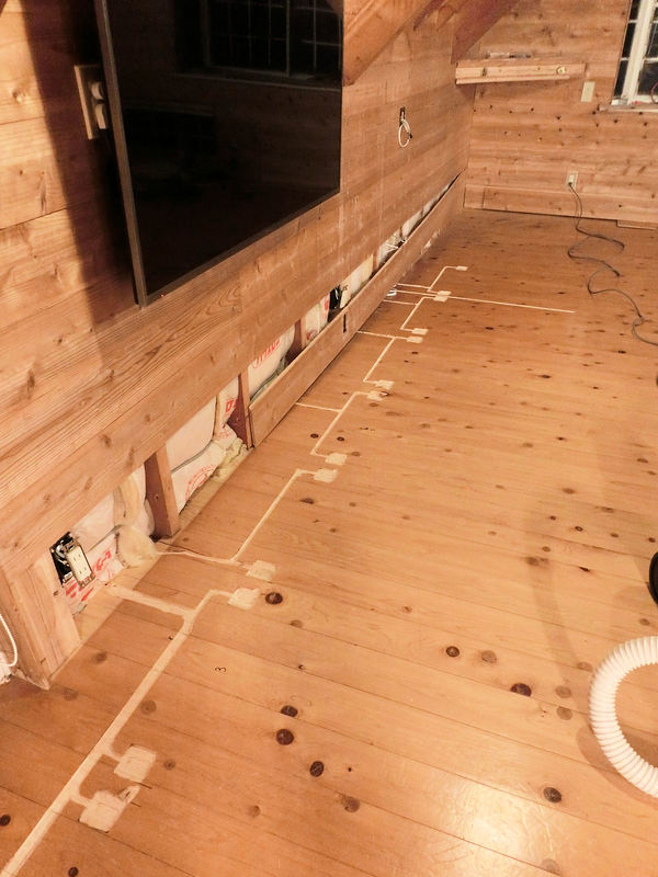
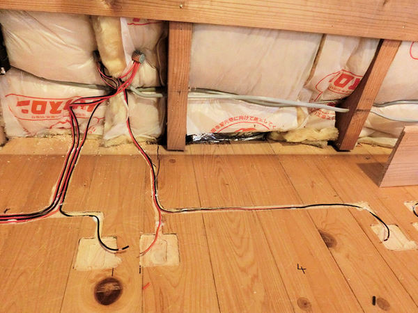
▲ まずは電気配線の準備です。ブレーカーボックスから壁に埋め込むコントローラーまで2コア電気ケーブルを使えました。壁の中に通さないといけないので、この作業がちょっと大変でした!壁を開かないといけないんです。使っていないブレーカーにつなぎます。
コントローラー用の穴を壁に開けました。やり方がコンセント用の穴と同じです。
I started this job by opening up the walls, and running some 2-core cable from the fusebox to a convenient point on the wall above the heating area. Then I cut a small hole in the wall there, into which the thermostat controller would fit.
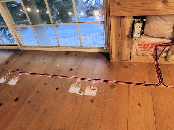
▲ 次は各50cm幅のヒーティングフィルムをコントローラーにつなぎました。シリーズ接続ではなくパラレル接続が必要です。配線が3mmほどの厚みとなりますので、電気ルーターで配線の位置を削りました。
Next came the super messy bit... I used an electric router to carve channels in the (old) floor, into which the cables would fit. Each 50cm-wide section of heating film requires its own cable connection, and these have to be joined on a basic parallel circuit (i.e. not in series!).
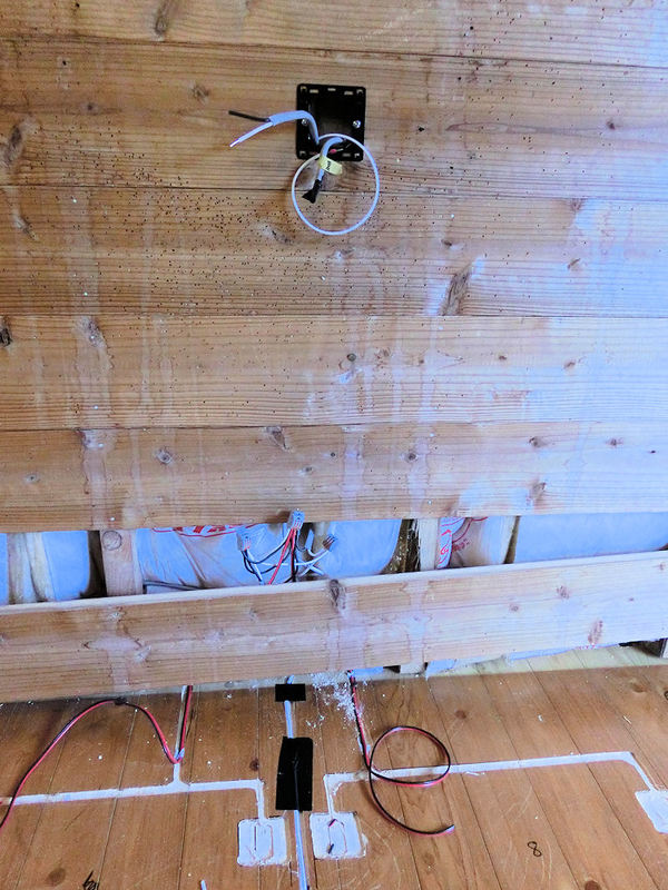
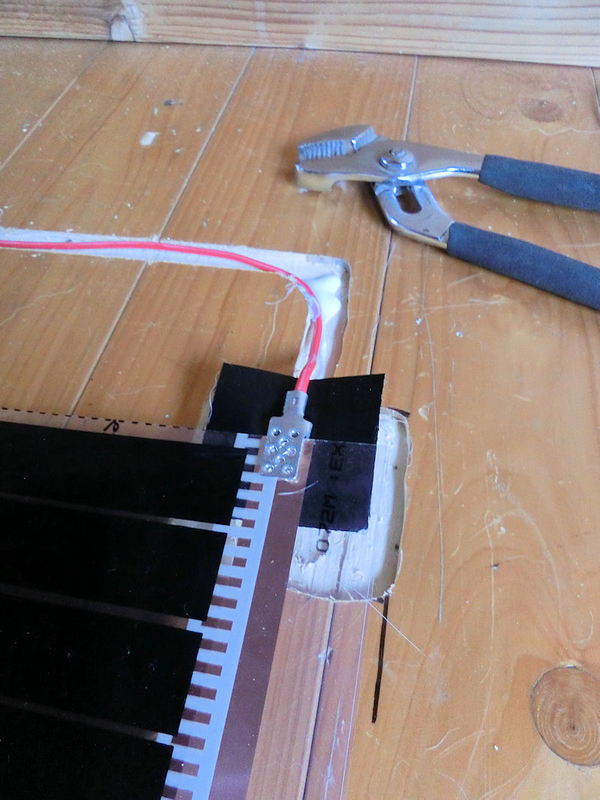
▲ この写真にはコントローラーの穴が見えます。右からくるケーブルがブレーカーにつなぎます。2本目のケーブルが下のコネクターにつなげて、各フィルム用の8本の赤/黒配線に分けました。
その白い配線(黒いテープが張っているところ)が気温センサー。コントローラー機のオプションパーツです。フィルムと同じようにフローリングの下に置きます。
Basically, you can see that each section of heating film has its own red & black cable, which are joined inside the wall using cable connectors. I had 8 strips of film, so two groups of 4 red wires each go into their own connector, and then those 2 connector wires finally meet up in another connector, which plugs into the back of the controller. The same is done for the black wires.
See this very detailed PDF guide on how to install underfloor heating.
One other thing I did was to run a thin temperature sensor wire (comes with the controller) in between 2 film sections, to monitor floor temperature. That's the white wire in the photo above, covered by black tape.
▲ 各フィルムには赤/黒の配線が必要です。ずれないようにホットボンドで固定しています。
I fixed each red and black wire inside its carved channel using a hot glue gun.
▲ この写真も同じです。2枚目と3枚目のフィルムのところに配線がつながっています。
It was a bit time-consuming, running wires to each of the 8 sections and cutting to length, but not hard.
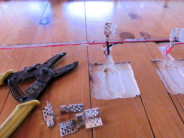
▲ 各配線にはフィルム用のクリップを写真のように付けないといけません。
Next thing to do is to add crimp connectors to the end of each wire, as shown in the photo above. I also added a little bit of metal solder, to make sure the connection was secure.
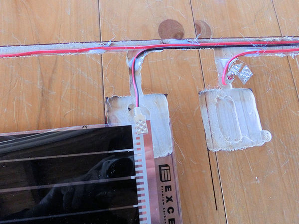
▲ フィルムを入れると銅のところにクリップを固く閉めます。
Then I used some strong pliers to squeeze each crimp closed around the heating film. As long as it connects properly through the copper strip, then your circuit is complete. You should test connections at this point.
▲ 最後にクリップの周りに防水テープを張ります。クリップの下に5cm²テープを付けて。。。
Finally, you should cover each crimp connector with a square of waterproof tape, to ensure it remains unaffected by spills and moisture.
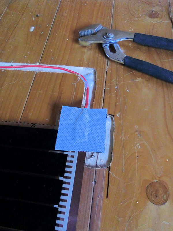
▲ 。。。そしてクリップの上にも張ります。これでこぼれた水から守れます。
One piece of tape underneath, and another on top, and it's time to connect the controller to the mains power, and test the system.
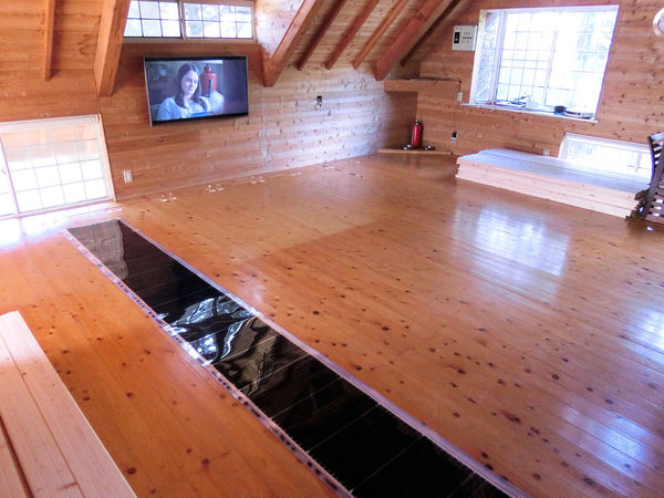
▲ ヒーティングフィルムの一枚目です。
This was the first 50cm-wide strip of heating film.
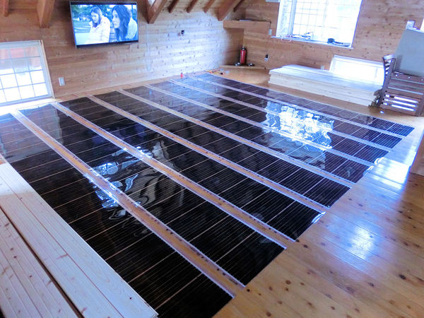
▲ 長さ4mの幅50cmフィルムを8枚で合計16m²の床暖房となります。各1m²には220Wになりますので、16m²で合計3520Wになります。ただし、私がミスしちゃった!ワットがこれでOKですが、アンプも大事でした。合計3520ワットなら100Vのシステムには約35アンプが必要です。
ブレーカー1個が20Aまでになります!そしてコントローラーも1個16Aまでです!OH NO!!!私が知らなかったです!
ということがブレーカー2個とコントローラー2個に分けないといけないです。残念!壁の中にまだ電気配線の作業がまた必要でした!
In total I planned for eight 4m-long strips of heating film, giving a total of 16m² of heating film. Since the wattage for each 1m² is 220W, this would give a total of 3.5KW for 16m². That was within the 3.6KW limit for a single controller. However, I completely failed to pay proper attention to the AMPS! Oh no!
On a 100V Japanese system, 3.5KW would require 35Amps, and a single fuse in the fusebox is limited to 20Amps. What's more, I hadn't noticed that a single controller was limited to 16A. Bugger! I'm an idiot.
So I feel like a fool for not spotting the problem, but at least it wasn't too difficult to fix. I opened up the walls again, and added a second controller. Thus, the 35Amps that were too much for a single controller, could be neatly split between 2 controllers. Well, almost.....
* If you are lucky enough to be able to connect to a 200V fusebox instead of a standard Japanese 100V fusebox, it will only use half the Amps, which is handy. Google how to calculate amps for more info. But note that you will need to order 200V heating film, not 100V.
▲ 2個のコントローラーのリミットが32Aですので、フィルムもちょっと小さくしないとね!はさみで簡単に切ることができます。
ラッキー!
Since the limit for one controller was 16Amps, and I currently was trying for 35Amps-worth of system, I had to remove a couple of metres of film to bring the total down to 32A (16A on each controller). So in the end, I was using 14m² of film instead of 16m², and using 2 controllers to power it - which works fine! Yay!
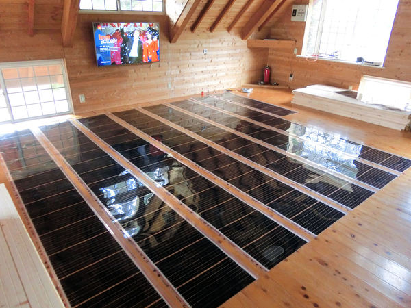
▲ 写真のように16m²のつもりから14m²に小さくしました。合計14m²の床暖房で約3100ワットになると、2個のコントローラー(と2個のブレーカー)に接続と各コントローラーが15.5Aになります。これでOKでした!フローリングを張る前に気が付いてよかった!
I'm just glad that I tested the system at every stage of the build. Nothing blew up or caught fire, it just kept tripping the fusebox, and eventually I was able to work out the reason! So, now you know - you should aim for about 14m² for a single controller, and you'll have a lovely efficient heating system!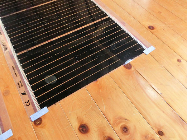
▲ 最後の作業ですが、各フィルムの反対側(配線接続ではない側)にまた防水テープを張らないといけないです。これで完成です!
Once you've tested your system works and cut any extra film off, you need to finish up the job by adding a bit of waterproof tape to the ends of each section, to close those copper strips off from moisture. And that's it!
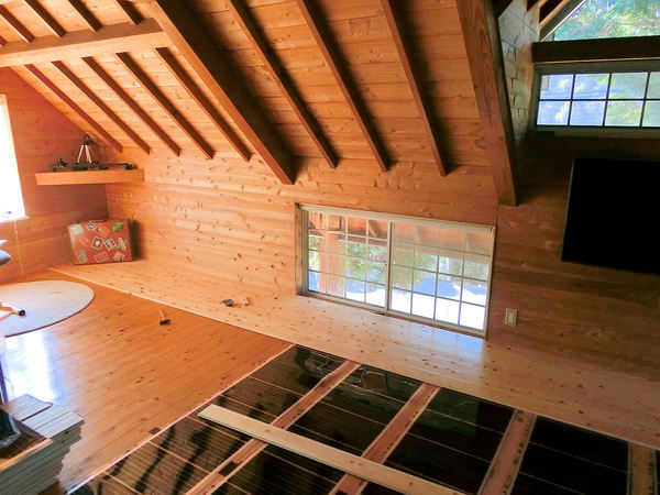
▲ 次の日から無垢フローリングを始めました。
I started covering the new underfloor heating system with some shiny new flooring the next day....
▲ 無垢フローリングの作業を次回から紹介します。お楽しみにしてください!
... but I'll save that for a new blog on another day!
アトリエにはいろんな作品を飾りたいので、展示用の棚を作ります。もちろんできるだけ節約したいので、安いパイン材でDIY作成です!
I need to make a variety of small shelves for the downstairs workshop, to show off the various things that can be accomplished with 3D printers. So I devised a simple way of making some easy floating shelves.....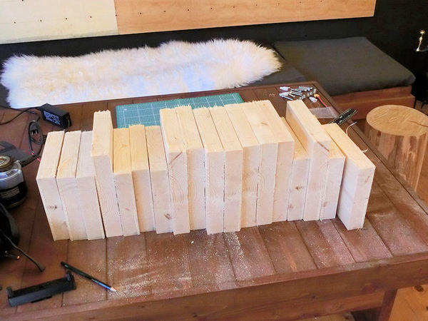
▲ まずは2サイズでカットしました。長いパイン材の板を20cmずつの棚にカットしました。そして、電気サンダーでスムーズにしました。
I bought a couple of 6-foot pine boards at the local DIY store, and trimmed off one curved edge to make them flat. Then I sliced them into 20cm chunks, which gave me 2 sizes of shelf (deep and narrow).
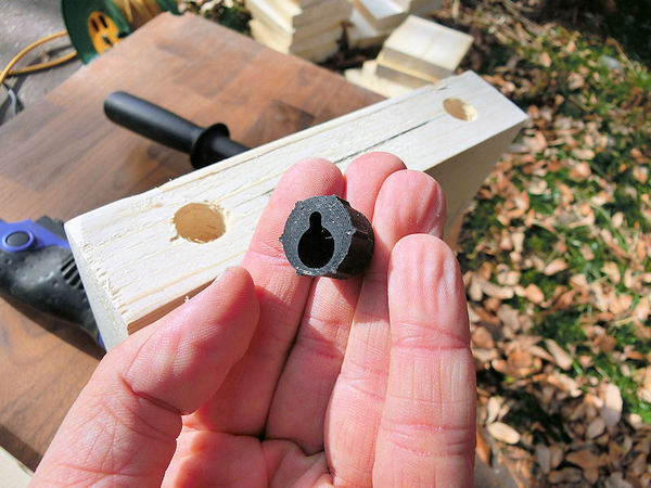
▲ 裏面に16mm穴を開けて、3Dプリントしたものを入れました。
I 3D printed lots of these clever little keyhole plugs, specifically designed for floating shelves and added two to the back side of each shelf.
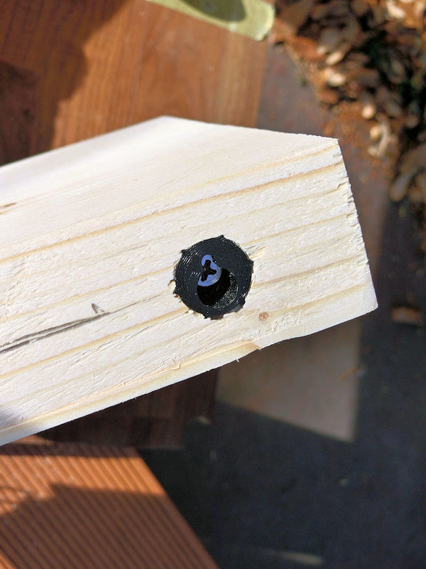
▲ 一本のネジが木材に入れて、2本目で壁に付けます。
One screw firmly attaches the plug to the wood of the shelf, and then a second screw is used in the keyhole slot to attach the shelf to the wall. It's probably not suitble for large, heavy shelves, but works fine for these smaller ones.

▲ 次は白にペイントしました。
A quick couple of coats of white paint....
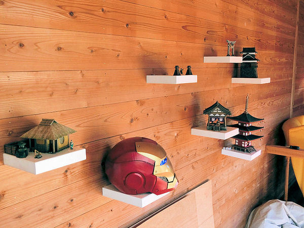
▲ ランダムで壁にアレンジしました。これで完成!
... and the first few shelves are complete. Easy!!
アトリエのオープンに近づいています!看板もできているし、インテリアのリフォームはあとちょっとですので、今回OPEN・CLOSEDの看板も作りたかったです。3Dプリントのアトリエになりますので、もちろん3Dプリンターで作成したいです!
The 3D print studio workshop is almost ready to open to the public now, since there's only a few little bits left to finish downstairs, so it seems like a good time to make an OPEN/CLOSED sign for the shop! Of course, since this will be a studio to display some cool 3D-printed objects, it seems only right to make the open/closed sign out of 3D-printed parts too!

▲ 見て目は普通でしょう?ただし、よく見ると面白いよ!
It looks pretty normal, yes? Well, wait for it......

▲ パーツは全部3Dプリント用の無料サイトからダウンロードして、プリントしました。最後にハンズマンから買った木材に載せました。耳をウォルナット色のワックス、ボディを透明ワックスで拭きました。
The parts for the sign were all downloaded from a free design on Thingiverse, and printed out in black and white plastic. Then I bought a suitable piece of rough-cut wood from my local DIY store (Handsman), and added antique waxes to the surfaces to age it and protect it.
https://www.thingiverse.com/thing:2087990
では、Are you ready?.......

▲ If you slowly turn it .....
▲ ..... the letters start to lift .....
▲ ..... and spin around .....
▲ ..... to make a CLOSED sign instead!
一階のホールはほとんどできていますが、やはりライトを変更したいですね!現在のライトは蛍光灯ですので、光は白で、bzzzzzzzの音もしますから雰囲気が合っていません。今回LEDのエジソン形の電球にします。
The downstairs hall is edging closer to completion now, so it's time to deal with those old lights. It used to be a dyeing workshop and then a painting studio, so I guess the bright fluorescent strip lights were adequate task lighting, but they are getting on a bit and so tend to buzz, and they have quite high power usage (320W for eight of them). Worst of all, the light they give off is a white light, which makes the room feel cold. So it's time to change them out....

▲ まずは3Dソフトで形を作ってみました。大引きの位置によって、二つに分けます。3メートルの丸い形に作りたいですが、そんなに大きい丸がないので、30cmずつのレール式にします。
I started this project by designing a large 3 metre diameter chandelier, with 18 retro-style Edison bulbs hanging down around the circumference. I suppose it's more of a rail lighting system than a chandelier, but the lights will be fixed in place. I originally wanted to make this a perfect circle from something like wood, but couldn't find any easy of creating this on a budget.... so I decided to make it out of 30cm straight sections joined together to make something that is close to a true circle.

▲ 最初に全部3Dプリントでしたかったんですが、重かったです。その代わりにDIY店で見つけった鉄レールを30センチ部分に切りました。
I bought several 2m metal rails from the local DIY store. I think they are commonly used as lightweight but strong systems for suspended ceilings, but they suited my purposes well too. So I carefully cut 30 pieces of 30cm length using a cutting blade on my rotary saw. Easy peasy so far!

▲ 作業中で手を切らないように鑢で綺麗にしました。
I then smoothed off any sharp edges with a file, so as not to cut my fingers later on!

▲ 電気配線の穴を開いてから、艶なしの黒でスプレーをしました。
Half of the pieces needed holes drilled in them for wiring, and then I sprayed them all with a matt black spray paint.

▲ 各レール部分を接続するところには3Dプリンターで30個のジョイントをデザインしました。上の写真はすべてのパーツとなっています。多いでしょう?!エジソン電球18個、中国から来たソケット18個、そしてレトロっぽい配線も集めました。
I'd been slowly collecting the various bits I needed for this project, so now I had 18 LED bulbs plus 18 shiny brass sockets, and some retro-style black cabling to match them. The joints between each section of rail were created to fit them exactly, and 3D printed slowly in the preceding days.

▲ 電気スイッチが二つありますので、1個の配線を抜いてライトの作成が半分ずつにしました。まずは天井から下がるところを図ってボルトとナットプレートを入れました。そして、ちょっとずつ各30センチ部分を下がりました。
次は電気配線の作業でした。これは結構簡単でしたので、スムーズに進みました。
Time to start fitting the light system, by fixing nut plates to the ceiling at various points. Then I fitted in cut pieces of long bolt, and hanging some custom-made hooks. Then I slowly slid in the short sections of railing, and started to join them together.

▲ 電球を入れて、スイッチの配線につながりました。電球のソケットにも1個ずつのスイッチもありますので、結構便利です。部屋の雰囲気や目的によって光が調整できます。
The next step was to run some cabling on the topside of the rails, and add 9 sockets using the retro-style twist cable. Each of these brass sockets has a separate on/off switch, so it's possible to adjust the light levels to fit whatever you're doing that day.

▲ 最後にレールを平行しました。あっちこっちに接続ジョイントが下がったところもありましたので、細かいプラスチックリボンで天井に付けました。これで平行に調整できましたので、ライトの半分終わりました。
The last thing to be done was to even up the railing. At a few joints the railing has started to droop slightly, because there were only 5 attachment points along the 4 meter circumference, so I added a few extra supports using long zip ties and some extra bits and bobs! This made the whole thing fairly level and even, and worked well enough for me.

▲ 1週間後に残りの半分も同じ風に完成できました!いかがでしょうか?
A week later I went back and completed the second half of the light in the same manner, and at last I had a finished lighting system! The height of the bulbs has been carefully alternated between high and low, just to create some extra interest and give it a more 'crafty' feel.

▲ やっぱり電球色のほうがいいですね!部屋の雰囲気も完全に変わりました!
I absolutely love it! The whole room is now bright and warm, and somehow still super cosy. I think lightbulb-coloured bulbs are such a great improvement on the glaring white light of strips lights.... plus the power consumption is now halved, even with 18 of those bulbs!
〒869-2226 熊本県阿蘇市乙姫2070-48
Aso City, Otohime 2070-48
Open from 13:00~17:00*
Fridays & Saturdays
(* if the door's closed, we might have popped out to walk the dog... back soon!)


")
Painted models available 塗装済の模型発売中!
Making garage doors ガレージの扉DIY作成
New side-project... a hobbit house! ホビットの家
Shops added to the shop ショップにお店
Repainting a (mini) car ミニカーのリペイント
Buying land in Otohime 乙姫で土地探し
Scale model of the Inaba Residence 稲葉家下屋敷の模型


 Shrine
 Temple
 Teahouse
 Castle
 Shops
Shops Houses
 Farm
Farm Other Buildings
 Walls & Fences
 Bridges
 Ponds
Ponds LED Lights
0 Comments :
Write a comment :